Sorry your browser is not supported!

You are using an outdated browser that does not support modern web technologies, in order to use this site please update to a new browser.

Browsers supported include Chrome, FireFox, Safari, Opera, Internet Explorer 10+ or Microsoft Edge.

DarkBASIC Professional Discussion / [STICKY] Learning to write Shaders

Author
Message
Green Gandalf
VIP Member
19
Years of Service
User Offline
Joined: 3rd Jan 2005
Playing: Malevolence:Sword of Ahkranox, Skyrim, Civ6.
Posted: 8th May 2010 00:51
Why don't you just copy the second object's UV coordinates (you'll need to check whether you want stage 0 or stage 1) onto the first object and do everything in the shader?

I'm rather baffled by CS4's use of two objects - seems inefficient to me.
_Pauli_
AGK Developer
14
Years of Service
User Offline
Joined: 13th Aug 2009
Location: Germany
Posted: 8th May 2010 00:57
Quote: "seems inefficient to me."


Yes, true. But I'm not planning to use very complex geometry so it will be ok.

Quote: "Why don't you just copy the second object's UV coordinates"


Do you mean in a model editor? Or by code?

Now the plot thickens, the fps decreases, and the awesomeness goes through the roof.
Green Gandalf
VIP Member
19
Years of Service
User Offline
Joined: 3rd Jan 2005
Playing: Malevolence:Sword of Ahkranox, Skyrim, Civ6.
Posted: 8th May 2010 01:21 Edited at: 8th May 2010 01:23
Quote: "Do you mean in a model editor? Or by code?"


By code. It is very easy if you know the vertex format of the two objects - use the vertexdata commands. You will need to loop through the limbs and, for each limb, copy the UV vertexdata of the lightmapped object into an array then copy the array data into the main object's UV data. This assumes they have the same vertex/limb structure.

Edit If you have a suitable model editor that will probably be quicker - unless you have lots of objects to process in which case a code solution will probably be quicker.
_Pauli_
AGK Developer
14
Years of Service
User Offline
Joined: 13th Aug 2009
Location: Germany
Posted: 8th May 2010 01:28
Thanks!
That was the kind of hint in the right direction that I needed! I'll try it with the code method first, because that will save me work afterwards.

Now the plot thickens, the fps decreases, and the awesomeness goes through the roof.
Dr Tank
15
Years of Service
User Offline
Joined: 1st Apr 2009
Location: Southampton, UK
Posted: 8th May 2010 02:46 Edited at: 8th May 2010 03:13
I think Cshop uses 2 objects because it can use many base textures, and many lightmap textures. I imagine the meshes are the same, so you could use 2 texture stages in a shader, if you kept it to 1 lightmap and 1 ordinary texture, but once you start using more than this it will become difficult.

I did a little experimentation. Made 3 cubes with 3 textures and lightmapped them. Opening up the .x files in Notepad, the meshes for the 2 objects appear to be the same, save the UV co-ords and materials. In each, there are 3 "objects" - one for each cube. Texture one side of one of the cubes with a different colour, and I see that these objects remain the same. What changes is the "MeshMaterialList" for the cube where I changed one of the faces. Check it out:


This is for a cube (12 triangle faces). I'm guessing the 1st # is the number of textures listed at the bottom. The second is the number of triangle faces, the next 12 numbers are the materials for each of the 12 triangle faces, and last is the list of materials, declared at the start of the .x file. Note how one of the faces is textured with material_3, and the rest with material_2.

So, unless you can think of a cunning trick, you'd need to write some kind of importer/converter.

I'd be interested to hear how it goes, because I'd love to be able to use CS maps without the sucky 2 object system.
Dr Tank
15
Years of Service
User Offline
Joined: 1st Apr 2009
Location: Southampton, UK
Posted: 8th May 2010 03:25 Edited at: 8th May 2010 03:26
Quote: "If you have a terrain textured with, for example, a single base texture plus a 12x12 tiled detail texture then if you are going to pre-render the whole terrain texture either you have lots of textures (assuming the terrain has lots of limbs) or a single enormous texture for the whole terrain. Perhaps I misunderstand what you mean?"

Not planning to use it like that. For terrain maybe i'd want to prerender a lighting map. What I was thinking about was doing a texture map for something dependent only on position on the skybox model, and getting dithering at the same time. I think it's doable, but won't gain much.

Quote: "Glad to see you're considering using volume textures - a greatly underused feature. Sounds like it's a good time for me to tidy up my old volume texture creation code. "

Sweet. Don't hurry on my account.
Green Gandalf
VIP Member
19
Years of Service
User Offline
Joined: 3rd Jan 2005
Playing: Malevolence:Sword of Ahkranox, Skyrim, Civ6.
Posted: 8th May 2010 14:14
Quote: "I imagine the meshes are the same, so you could use 2 texture stages in a shader, if you kept it to 1 lightmap and 1 ordinary texture, but once you start using more than this it will become difficult."


I guess so.

Quote: "What I was thinking about was doing a texture map for something dependent only on position on the skybox model, and getting dithering at the same time. I think it's doable, but won't gain much."


Still not sure what exactly is being pre-rendered here. Perhaps all will become clear when you've got something working.

Quote: "Don't hurry on my account."


The main things holding me up are some obscurities in the MS DX9 SDK docs - I'm having to use trial and error to work out what some of the flags are exactly. Two days ago I reported one apparent error to MS which they have since confirmed and say will be fixed. We'll see. My old volume texture creating program (created 30 months ago!) works but is a bit of a clumsy hack. It really needs a C++/DLL wizard (like IanM ) to make something more elegant.

The main reason I'm working on this volume texture thing is that I need home-made horizon map volume textures for my self-shadowing terrain shader and I'd like to include it in the shader demo so users can make their own horizon maps. At the moment my horizon maps are created using a rather untidy sequence of programs which are best kept hidden from public view.
_Pauli_
AGK Developer
14
Years of Service
User Offline
Joined: 13th Aug 2009
Location: Germany
Posted: 8th May 2010 15:34 Edited at: 8th May 2010 15:37
So I have the copying of the UV coordinates done and working.
You can see it in this snippet here: (I know it's DarkGDK, but maybe you can still guess what it does)


I can see that this works, when I texture the map object with the lightmap image to stage 1.
But then I tried to apply this simple shader, that should blend the two stages together:


And suddenly I get the strangest results! Take a look at the attached screenshot.
It seems like the whole scene geometry collapses in one point! I have no idea what could cause this...
This does not happen when I don't copy the UV coordinates.
Any hints? Did I miss something?

Now the plot thickens, the fps decreases, and the awesomeness goes through the roof.

Attachments

Login to view attachments
Green Gandalf
VIP Member
19
Years of Service
User Offline
Joined: 3rd Jan 2005
Playing: Malevolence:Sword of Ahkranox, Skyrim, Civ6.
Posted: 8th May 2010 16:02
Have you added UV1 coordinates to your map object? If it doesn't already have them you'll need to change its FVF format.

For example, if your map object is the default FVF format 274 (XYZ + NORMALS + TEX1) you'll need to change it to 530 (XYZ + NORMALS + TEX2) using convert object FVF. The FVF component TEXn means the object has n sets of UV data so you need TEX2.

If you try to copy data into a UV stage which doesn't already exist you'll probably overwrite some existing data which would explain your strange results.
_Pauli_
AGK Developer
14
Years of Service
User Offline
Joined: 13th Aug 2009
Location: Germany
Posted: 8th May 2010 16:10
Oh, Green Gandalf Thank you so much!
That totally did it!
I just added this line:


And it works perfectly now! I guessed it had something to do with the FVF, because the results looked like there was a lot of data corrupted.

Problem solved.

Now the plot thickens, the fps decreases, and the awesomeness goes through the roof.
TuPP3
17
Years of Service
User Offline
Joined: 26th Jan 2007
Location: [+--]FINLAND
Posted: 10th May 2010 18:18 Edited at: 10th May 2010 18:21
Hello everyone, I looked into some EVOLVED shaders and discovered that shaders are darn powerful, for example shader can achieve effect of resizing whole object!

So I've been wondering one use for shader, do you know the effect what happens when you look throught scope or such telescopic sight, so that if your eye is aligned incorrectly you start seeing this black ring until the view is completely blocked.
Or if your eye is too close or too far of the lens, view area gradually gets smaller obstructed by this "black ring".

Like this:


So i'm asking could this be done with shaders? How difficult would you rate it compared to alternative methods without shader?

I can't code shaders, I know nothing about C++ so I'm merely just asking this for curiousity, and I haven't come up with any other solution for this effect than shader use.
Garion
16
Years of Service
User Offline
Joined: 7th Dec 2007
Location: Poland
Posted: 11th May 2010 00:48
A fish eye effect you mean I think I don't think it would be too hard to code one, it's basicly a really large FOV from what I know...
TuPP3
17
Years of Service
User Offline
Joined: 26th Jan 2007
Location: [+--]FINLAND
Posted: 11th May 2010 01:11 Edited at: 11th May 2010 01:12
Nope, I mean that black "ring" that is blocking the view, not the view itself.

This could be basically achieved manually by making a mask plane in front of the scope, and resize the black mask texture according the difference between player head(eye) and the scope.

So that when you move your player head backwards in the game the mask texture is shrunken, thus gradually blocking the view.
And also scroll the mask texture coordinates when head is moven left, right, up or down.
Green Gandalf
VIP Member
19
Years of Service
User Offline
Joined: 3rd Jan 2005
Playing: Malevolence:Sword of Ahkranox, Skyrim, Civ6.
Posted: 11th May 2010 12:37
Isn't that "ring" merely the ring surrounding the eyepiece of the telescope? Why do you want to change that? Also, isn't the telescope a standard object which you can move backwards and forqwards in the usual way? I would simply use a mask texture corresponding to the view through the telescope. Everything else should be rendered in the usual way.

I confess I'm rather baffled by your request.
TuPP3
17
Years of Service
User Offline
Joined: 26th Jan 2007
Location: [+--]FINLAND
Posted: 11th May 2010 17:49 Edited at: 11th May 2010 17:50
Nope, I don't mean the scope itself either.

Maybe I explained it wrong or some of you don't remember what its like to look throught scope(rifle in this case).

I found good video to explain what pictures didn't achieve:
http://www.youtube.com/watch?v=S2xh2U2GmhU&feature=related

And to connect that with my game here is some edited images how it should look, and the bottom one shows how it looks now:
http://i160.photobucket.com/albums/t187/TuPP3/scope.png?t=1273589019
(I'm using 2 cameras for the scope and environment)

So again, you must look throught the scope your eye perfectly aligned to see throught.
Green Gandalf
VIP Member
19
Years of Service
User Offline
Joined: 3rd Jan 2005
Playing: Malevolence:Sword of Ahkranox, Skyrim, Civ6.
Posted: 11th May 2010 18:22
Quote: "Maybe I explained it wrong or some of you don't remember what its like to look throught scope"


Probably right on both counts.

I need to experiment with a real scope to see exactly what's required - or to work out the optics on pen and paper. Not sure which is easier.

I guess it's not really a black ring that you mean - it's in fact the inside surface of the scope itself (which may be blackened to reduce unwanted internal reflections).

I understand what you mean now.

Just looked through one lens of our binoculars and the "black ring" does look like the inside surfaces of the scope - but the ring only gets smaller as you move away or sideways, not as you get closer.
TuPP3
17
Years of Service
User Offline
Joined: 26th Jan 2007
Location: [+--]FINLAND
Posted: 11th May 2010 19:35 Edited at: 11th May 2010 19:41
I have 2 rifle scopes myself, but they both are pretty old (5-10 years) so I'd have to see some new models and see is their view shrunken when seeing too close or far.
That could be probably intended effect so that the shooter wouldn't keep his/her eye too close to the scope when shot, causing serious injury.

I noticed too that its the inside of the scope while ago when I explored this "effect", and I came up with alternative solution before I knew anything about shaders.

[½offtopic]
My camera is aligned with 2 objects, 1st at the start of the scope and the 2nd one at the end of the scope.
1. I position the camera to the 1st object
2. I point the camera to the 2nd object
3. I position the camera to the second object

So I though it like this(another of my "illustrative" images):
http://i160.photobucket.com/albums/t187/TuPP3/TRG42/Untitled-1.png?t=1273594410
So that I rotate the second camera, thus seeing inside of the scope and blocking the view gradually.
I don't remember did I try this as I tried quite many alternative solutions to this.
[/½offtopic]

But as we are talking about shaders, I think it could be done like this:
Create plane object in front of the scope, texture it with mask like this and strech it to fit the scope:
http://i160.photobucket.com/albums/t187/TuPP3/mask.png?t=1273593143

Then use shader to modify the texture UV coordinates according to the player head position and scope position.
Move the mask and resize it.
And then manually disable the camera when the mask reaches its limits so that it wouldn't dublicate the hole another time.
artu
13
Years of Service
User Offline
Joined: 11th May 2010
Location:
Posted: 12th May 2010 01:08
Awesome.videos to learn thanks!
Funny Games

artu
_Pauli_
AGK Developer
14
Years of Service
User Offline
Joined: 13th Aug 2009
Location: Germany
Posted: 12th May 2010 19:21 Edited at: 12th May 2010 19:22
Can someone help me with this basic vertex lighting shader?


Instead of doing vertex lighting on the objects, it just draws them black! I have no idea why!
Maybe someone can take a look into it and help me out.

Now the plot thickens, the fps decreases, and the awesomeness goes through the roof.
Green Gandalf
VIP Member
19
Years of Service
User Offline
Joined: 3rd Jan 2005
Playing: Malevolence:Sword of Ahkranox, Skyrim, Civ6.
Posted: 12th May 2010 20:09
Here's your problem:


Think about it. If you're still stuck, post back. Your shader works when you've fixed that.
_Pauli_
AGK Developer
14
Years of Service
User Offline
Joined: 13th Aug 2009
Location: Germany
Posted: 12th May 2010 20:38 Edited at: 12th May 2010 20:39
So this means the bigger the distance the smaller the attenuation.
But I don't really get what's wrong about that. I mean this will get closer to zero (black) the higher the distance from the vertex to the light is!
Even if I set attentuation to 1 for testing, everything is still black!

Edit: Sorry if I don't see the obvious right now, but I'm not the best in shaders (and math)...

Now the plot thickens, the fps decreases, and the awesomeness goes through the roof.
Green Gandalf
VIP Member
19
Years of Service
User Offline
Joined: 3rd Jan 2005
Playing: Malevolence:Sword of Ahkranox, Skyrim, Civ6.
Posted: 12th May 2010 21:56 Edited at: 12th May 2010 21:57
Quote: "Even if I set attentuation to 1 for testing, everything is still black!"


It's not black for me - that was the first thing I tried. Perhaps you are looking at the wrong side of your object? Here's a screenshot from Dark Shader with just that one change:


Quote: "So this means the bigger the distance the smaller the attenuation.
But I don't really get what's wrong about that. I mean this will get closer to zero (black) the higher the distance from the vertex to the light is!"


Yes, but what distances are you using? You need to ask yourself questions like "How bright should a pixel on my object be at a distance of 100 units". Your present formula makes it 0.01 or 1% - which is almost indistinguishable from black. If you want it to be 50% illuminated at that distance then you need something like:


So there are at least two things to check:

1. the direction of your light from the target pixels
2. the actual distance and desired illumination level of your object.

Attachments

Login to view attachments
_Pauli_
AGK Developer
14
Years of Service
User Offline
Joined: 13th Aug 2009
Location: Germany
Posted: 12th May 2010 22:19 Edited at: 12th May 2010 22:55
Thanks for your help, I got it working now!
After setting a higher attenuation everything is fine.

Next step: Per-Pixel Lighting


Edit: Oh, one more question! Do you know how to pass arrays of vectors (like the light positions) to a shader?

Edit 2: I just tested this vertex lighting with a simple map object (from CShop 4) and the lighting suddenly has no effect on it (completly black)! Other models (e.g. a teapot model) work fine, but Cartography Shop 4 maps don't! What could be the problem?

Edit 3: CShop issue fixed, had to set object normals.

Now the plot thickens, the fps decreases, and the awesomeness goes through the roof.
Green Gandalf
VIP Member
19
Years of Service
User Offline
Joined: 3rd Jan 2005
Playing: Malevolence:Sword of Ahkranox, Skyrim, Civ6.
Posted: 12th May 2010 22:56
Quote: "Do you know how to pass arrays of vectors (like the light positions) to a shader?"


Not offhand. One way is to use the rows (columns?) of a matrix4. Another is to use the method made available with Dark Shader (I can't recall the precise details). I'll try to find out and report back.

Quote: "and the lighting suddenly has no effect on it (completly black)! What could cause this?"


Wrong or absent normals is the most likely reason. Check the structure of your object - you need to know the FVF format. Look at convert object fvf for available formats and make memblock from mesh + make mesh from object for how to find your object's fvf.
_Pauli_
AGK Developer
14
Years of Service
User Offline
Joined: 13th Aug 2009
Location: Germany
Posted: 13th May 2010 18:34 Edited at: 13th May 2010 18:36
Ok, I have the array issue solved, although it's in DarkGDK, so it might not help DBPro users. It works by accessing the shader effect through Direct3D. I have a recent thread about this on the DarkGDK board.

But I have another question:

How can I pass a texture from one pass to another?
I'm thinking about creating a blank 2D sampler, write data (e.g. normals, depth,...) as color values to it in the first pass and read that data in the second pass. I want to build a g-buffer with this. I have the data setup done, but right now it just outputs to color0 and color1 in the first pass' pixel shader. I have no clue how to put that into a sampler...
Any ideas or hints?

Now the plot thickens, the fps decreases, and the awesomeness goes through the roof.
Dr Tank
15
Years of Service
User Offline
Joined: 1st Apr 2009
Location: Southampton, UK
Posted: 17th May 2010 06:31 Edited at: 18th May 2010 19:55
Sorry dude. No idea about extra passes.

I've been making this. Shader version of Sterographic Projection camera. Works pretty well. Not that fast. Have plans to do version(s) with less in the pixel shader.

edit: I made an error with setting camera aspect. Aspect is set as 1.666666, but widescreen should be 1.777777.


DBP code:


shader:


I attached the project folder in a rar.

Attachments

Login to view attachments
Garion
16
Years of Service
User Offline
Joined: 7th Dec 2007
Location: Poland
Posted: 17th May 2010 13:29
Nice!
Dr Tank
15
Years of Service
User Offline
Joined: 1st Apr 2009
Location: Southampton, UK
Posted: 18th May 2010 19:43 Edited at: 18th May 2010 19:53
Thanks. This version is nicer.

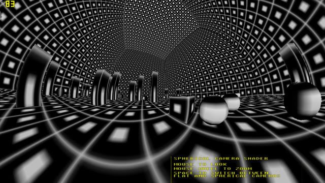
Now uses a cube map, so can zoom out more, and see greater than 180 degrees. You can zoom in and out with the mouse wheel. You can switch between special "spherical" camera and standard flat one for quick comparison. Note how if you zoom in, the two cameras are basically the same. Zoomed out, the spherical cam sees a wider angle.

Please be aware that to achieve a flat camera perspective, using a standard single camera in DBP will be much more efficient. Also for a spherical camera, for small FOV, it is better to use a single extra camera (as in previous example). Note the pixellation in this version when you zoom in.

I'm tempted to make a version with seamless unblurred zoom combining these two techniques next. Also add other camera types, and seamless transitions. For example, a hybrid of flat and spherical cameras could achieve a balance between the distortions of each.


Compressed folder containing .dbpro, .dba and .fx files is attached. No external media apart from the shader. For quick reference, i append the DBP code and the shader:

DBP program:


shader "FX/flat switch.fx":

Attachments

Login to view attachments
_Pauli_
AGK Developer
14
Years of Service
User Offline
Joined: 13th Aug 2009
Location: Germany
Posted: 19th May 2010 15:00 Edited at: 19th May 2010 15:28
Great work Dr Tank!
This reminds me of those fisheye cameras they use in skateboarding-videos!

I have a big problem implementing Depth Shadow Mapping. Well, I used to get this to work some time ago... But I encountered some strange issues that really give me headaches!
Any helpful input is very appreciated!

First of all, here is the shader code:


To explain: I pass the lights view matrix from the program to the shader by constructing a view matrix (make view matrix4) and setting it as effect constant matrix.
I just put the output color of the scenes pixel shader to either be the texture color (if pixels depth is <= stored depth in shadow map) or black for testing.
I made this by following Riemers XNA tutorials.

Now the problem is that the whole frustum of the lights camera is painted in the plain texture colors, even when there should be a shadow (pixel depth > stored depth)! The rest of the scene is black like it's supposed to be.
The depth map from the first pass ("Light" technique) is correct as seen by pasting the lights camera image to the screen onto the final render.
When I change the output color in the scenes pixel shader from the texture color to the sampled shadow map (=stored depth), it seems to be correct too and looks almost like the real shadow.
Another problem I noticed is that the same image gets projected in both directions from the light!

I know about the basic principles of Shadow Mapping but just don't see what's wrong here.
I'd be so glad if someone could help me out here! It's really driving me mad!

EDIT:

Oh god, sometimes just writing about something helps. I just got it working on my own. Sorry, didn't want to cause any trouble here...
The solution to my problem was this:
- I didn't really initialise the output color (tmpColor) in the scenes pixel shader. It's now the texture color * ambient right away.
- I did float d = input.samplePos.z / input.samplePos.w, but it should be float d = input.samplePos.z / MaxDepth to get the real depth of the current pixel.
- If that depth (d) is smaller than the stored depth and d >= 0 (to not draw the back-projected shadow map) then tmpColor is the texture color.


EDIT 2:

Any ideas on how to shape the light without using an additional texture (like in the mentioned tutorial above)?
I just want to give it a spot-like shape and not that sharp-edged light frustum borders.

Now the plot thickens, the fps decreases, and the awesomeness goes through the roof.
Green Gandalf
VIP Member
19
Years of Service
User Offline
Joined: 3rd Jan 2005
Playing: Malevolence:Sword of Ahkranox, Skyrim, Civ6.
Posted: 19th May 2010 15:38
Quote: "Any ideas on how to shape the light without using an additional texture (like in the mentioned tutorial above)?
I just want to give it a spot-like shape and not that sharp-edged light frustum borders."


Use the dot product of the light's direction vector and the pixel's direction vector from the light's position (also, normalize both vectors and make sure they both point the right way). You can then use the result to get various radial attenuation effects.
The Slayer
Forum Vice President
14
Years of Service
User Offline
Joined: 9th Nov 2009
Playing: (Hide and) Seek and Destroy on my guitar!
Posted: 30th May 2010 14:36
Hi guys, I'm working on a space game. The idea would be to have planets with an atmosphere surrounding them, so you could fly through the atmosphere and land on the planet (sort of). So, I was looking for an atmosphere shader and stumbled upon this one I found on the internet. I loaded the effect in DarkShader and had to rem out two lines to get it compiled. I don't know if the shader works (didn't try it out yet), so if anyone could have a look and try the shader out or get it to work? Also, why did I have to rem out those two commands, and what do they do exactly? Any help is much appreciated.

Here's the shadercode:


Cheers

Slayer rules!!! Yeaaah, man!
Green Gandalf
VIP Member
19
Years of Service
User Offline
Joined: 3rd Jan 2005
Playing: Malevolence:Sword of Ahkranox, Skyrim, Civ6.
Posted: 30th May 2010 16:55
I've encountered the same problem with shaders provided by the latest version of FX Composer. I believe the problem may be that the latest version of FX Composer uses the DX10 version of the shader compiler. This has backwards compatibility for earlier DX9 shaders but also seems to support some extra commands introduced by DX10. Another possibility is that the shader is designed for an application which preprocesses certain lines before passing the shader to the shader compiler.

To answer your specific questions:

First line:


I've no idea yet.

Second line:


That seems to be a shortened version of the following familiar DX9 filtering specs:


By commenting it out you're relying on the defaults assumed by either your application or the shader compiler. These probably assume the linear option anyway.

I'll try to confirm these interpretations from the DX SDK and report back later.
The Slayer
Forum Vice President
14
Years of Service
User Offline
Joined: 9th Nov 2009
Playing: (Hide and) Seek and Destroy on my guitar!
Posted: 30th May 2010 18:13
Thanks for looking into that, Green Gandalf! You're the best!

I just checked the site were I found that shader, and it seems that the shader was made in FX Composer, if that might help you out?

I guess that the first command remmed out, has something to do with the coordinates of the light (sun).

Quote: "By commenting it out you're relying on the defaults assumed by either your application or the shader compiler. These probably assume the linear option anyway."

So, commenting it out won't be a problem for the shader to work? Is that what you're saying? The shader will use linear filtering as default?

Cheers

Slayer rules!!! Yeaaah, man!
Green Gandalf
VIP Member
19
Years of Service
User Offline
Joined: 3rd Jan 2005
Playing: Malevolence:Sword of Ahkranox, Skyrim, Civ6.
Posted: 30th May 2010 19:05
Quote: "So, commenting it out won't be a problem for the shader to work? Is that what you're saying? The shader will use linear filtering as default?"


Quite possibly, but I wouldn't rely on it. It's safer to be definite and use that three line snippet I gave before.
_Pauli_
AGK Developer
14
Years of Service
User Offline
Joined: 13th Aug 2009
Location: Germany
Posted: 31st May 2010 12:46 Edited at: 31st May 2010 12:46
Do you know how to check if a texture/sampler exists in HLSL?
I'd like to check if a certain texture stage of an object actually has a texture applied to it.
Think of an object with the diffuse texture in stage 0 and a lightmap in stage 1. Now if I apply a shader to it that multiplies both components, an object that doesn't have a lightmap will be black (lightmap color = 0). But I want it to have an ambient color instead.
Thanks in advance.

Now the plot thickens, the fps decreases, and the awesomeness goes through the roof.
Green Gandalf
VIP Member
19
Years of Service
User Offline
Joined: 3rd Jan 2005
Playing: Malevolence:Sword of Ahkranox, Skyrim, Civ6.
Posted: 31st May 2010 19:24
Quote: "I'd like to check if a certain texture stage of an object actually has a texture applied to it."


Not offhand.

But why would you need to do that? Don't you know whether or not a lightmap has been applied? And if you do know just use another technique that does what you want? Also, if that's all you're doing you don't need a shader.
_Pauli_
AGK Developer
14
Years of Service
User Offline
Joined: 13th Aug 2009
Location: Germany
Posted: 1st Jun 2010 13:06
Quote: "Don't you know whether or not a lightmap has been applied?"


Well, no I don't because it's one shader that is applied to every object in the scene for lighting. (like in Unified Lighting I think...)
I was trying to combine lightmaps with a Shadow Mapping spot light.
But I have the desired results by doing this now:


I know that it isn't really correct, because the ambient color gets added to a lightmapped object, too. That makes it brighter than it should be. I don't have a work-around for this right now...

Next thing I'm working on is including Normal Mapping. I calculate the normal factor like this (called diffuse):


Very basic, I know. Just want to get the simple stuff done...
How shall I combine this factor with the pixel color equation from above?

Now the plot thickens, the fps decreases, and the awesomeness goes through the roof.
Green Gandalf
VIP Member
19
Years of Service
User Offline
Joined: 3rd Jan 2005
Playing: Malevolence:Sword of Ahkranox, Skyrim, Civ6.
Posted: 1st Jun 2010 13:58
Quote: "Well, no I don't because it's one shader that is applied to every object in the scene for lighting."


I see. But why use only one shader? One solution is to use two shaders - one for lightmapped objects, one for the others.

Another solution to your problem is to use a third texture for each object (this can be as small as your GFX card will support, e.g. 1x1 pixels). Set this texture to a white image for nonlightmapped objects and black for lightmapped ones. Read this texture into a variable called ambientMask. Then use something like


Yet another solution is to set the ambient light to zero when you create the lightmap - but this might cause problems if you have lightmapped objects without shaders applied to them.

Quote: "How shall I combine this factor with the pixel color equation from above?"


I don't know - unless you tell me which light it refers to. If it refers to the light used for the shadowmapping then just use something like

_Pauli_
AGK Developer
14
Years of Service
User Offline
Joined: 13th Aug 2009
Location: Germany
Posted: 1st Jun 2010 14:22 Edited at: 1st Jun 2010 14:24
Ok, thanks!
I think I'm going with the ambient-texture thing but right now the Normal Mapping bothers me more...
The Normal Mapping now works for the spot light ('inside the spot'). But now there is no Normal Mapping outside of the spot light.
What I'd like to do now is to have Normal Mapping for the rest of the scene too, but with a global light direction instead of the Shadow Mapping spot light.
I have the setting of the light direction vector already done. (setting light_dir to normalize( input.pos - light_pos ) if inside the spot and setting it to a global light direction if not)
Then the normal factor (diffuse) is computed based on that.

Now I don't know how to change the final pixel equation
I tried this:


But as one might expect that doesn't work, because the whole thing depends on the normals now, so the lightmap and ambient has no effect.
How shall I change that?

Now the plot thickens, the fps decreases, and the awesomeness goes through the roof.
Green Gandalf
VIP Member
19
Years of Service
User Offline
Joined: 3rd Jan 2005
Playing: Malevolence:Sword of Ahkranox, Skyrim, Civ6.
Posted: 1st Jun 2010 15:11 Edited at: 1st Jun 2010 15:13
You need to keep asking yourself whether you are adding a new light or modifying an existing one. If you are adding a new light then you have to add the new lighting to the existing lighting. For example:


The lighting in that equation is all contained within the brackets and assumes four light sources:

- the lighting from a light source which casts shadows (or a spot light)
- the lighting from the lightmap
- the ambient light
- the bumpmapped lighting from an additional directional light.

That's obviously an oversimplification since it doesn't use a light colour and doesn't take account of the changes we've already discussed. It also adds the directional lighting to the "spot" component - but you can remove that by using something like "+ (1-spot)*diffuse" instead of just "+ diffuse".

If you want to modify an existing source of light then it's that term that you'll need to modify - usually by multiplying that term by a suitable number.

One final thing. If you're merely trying to make the lightmapped areas look bumpmapped then it's the lightmapped term that needs to be changed. A simple, but not very satisfactory, way to do this is to just multiply "lightmap" by "diffuse". There are two things wrong with this: (a) it darkens the lightmapping (this is easy to adjust though), and (b) it darkens it far too much if the single directional light has a direction completely different from that used when the lightmap was created (this is particularly relevant if the lightmap used several different positional lights in widely different positions).

What you need is a good compromise. I haven't tried this myself so you'll have to be a guinea pig (you can tell it's a wet gardening day outside here ). What I have in mind is to use a fixed light direction in tangent space - I'm assuming your normal mapping is already using that space of course. You then just modify the lightmap term by the new diffuse value, possibly multiplied by a factor 2 or so to reduce the overall darkening effect.
_Pauli_
AGK Developer
14
Years of Service
User Offline
Joined: 13th Aug 2009
Location: Germany
Posted: 1st Jun 2010 19:22 Edited at: 1st Jun 2010 19:23
First of all, thank you so much for taking the time to explain all this!
I think think I'm very close to finishing this shader.
And I've read a few articles in the meantime (mostly Gamasutra ones), especially about tangent space.
Well, I had some strange results with the Normal Mapping so I went back to basics and wrote the simplest Normal Mapping shader I could think of. I ended up with this:


I thought everything was fine. But then strange things happend!
It seems like something is wrong with calculating the world position of the vertex. The lighting (like the normal based brightness) somehow rotates with the object! (made a small test scene with just a constantly rotating cube)
As I said, the vertex position isn't really transfered from object to world space! And I just can't tell what's wrong!!! I mean I'm doing float3 worldPos = mul( input.pos, mW ) as it should be...

I hope you can help me and I get this out of the way quick so I can get back to the real shader.

Now the plot thickens, the fps decreases, and the awesomeness goes through the roof.
Green Gandalf
VIP Member
19
Years of Service
User Offline
Joined: 3rd Jan 2005
Playing: Malevolence:Sword of Ahkranox, Skyrim, Civ6.
Posted: 1st Jun 2010 19:44
Try this. You need to convert your light vector to object space before converting to tangent space coords. Since it's in world coords you need the WorldInverse matrix. I think this is correct now (I've just added two lines). Post back if it's still wrong.

_Pauli_
AGK Developer
14
Years of Service
User Offline
Joined: 13th Aug 2009
Location: Germany
Posted: 1st Jun 2010 19:58
Nice, it works now.
Every tutorial on Normal Mapping that I've gone through never mentioned converting the light vector to object space!
I guess I would have spend ages sorting this out, so thanks a lot!

Now I'm going back to my scene lighting shader. Chances are high that there may be a few other issues to solve

Now the plot thickens, the fps decreases, and the awesomeness goes through the roof.
Green Gandalf
VIP Member
19
Years of Service
User Offline
Joined: 3rd Jan 2005
Playing: Malevolence:Sword of Ahkranox, Skyrim, Civ6.
Posted: 26th Aug 2010 18:33
Sixty Squares

In answer to your question (on another thread) about basic per pixel lighting for a single positional light. Here it is.


Any questions, just ask.

Quote: "Take your time, I'll watch for your post"


I did I'm afraid. It took me a painfully long time to realise that I'd declared eyePosition as a float instead of a float3. Had to resort to testing it in FX Composer to find out was going wrong with the specular lighting - I knew it was wrong but couldn't see why. Should be OK now though.
Sixty Squares
17
Years of Service
User Offline
Joined: 7th Jun 2006
Location: Somewhere in the world
Posted: 26th Aug 2010 20:46 Edited at: 26th Aug 2010 20:48
Quote: "I did I'm afraid. It took me a painfully long time to realise that I'd declared eyePosition as a float instead of a float3. "


It's alright, thanks for taking the time to post

I'm afraid I've run into a problem with the shader. For some reason the sphere is turning out black using the diffuse technique. Under the specular technique the sphere is also black but there is a red highlight. Here is my DBPro code:


I looked into the problem and found that when I changed this line in the shader:


to this (just to test and see if it would light at all)


the object was white as expected AND properly lit. I'm guessing that something's up with the texture look-up . Any ideas?


Guns, cinematics, stealth, items and more!
Green Gandalf
VIP Member
19
Years of Service
User Offline
Joined: 3rd Jan 2005
Playing: Malevolence:Sword of Ahkranox, Skyrim, Civ6.
Posted: 26th Aug 2010 21:38 Edited at: 26th Aug 2010 21:42
Your code works fine for me.

Are you sure you've got the texture in the right place - and got the right name for it? I got exactly your problem when I accidentally got the image filename extender wrong, e.g. jpg instead of bmp.

Edit Actually it was the other way round. I'd put bmp instead of jpg for the image I used. Now why didn't DBPro give a run time error? I thought it usually said something like "couldn't load image at line xxx" or is that objects? I'll investigate.
Green Gandalf
VIP Member
19
Years of Service
User Offline
Joined: 3rd Jan 2005
Playing: Malevolence:Sword of Ahkranox, Skyrim, Civ6.
Posted: 26th Aug 2010 21:47 Edited at: 26th Aug 2010 22:07
Well, what do you know? It seems that DBPro only gives the load image error for certain image formats. Here's the runtime error I get when I deliberately use png by mistake:


BUG REPORT COMING UP!!

Edit On investigation it seems that dds, png and tga files all give the correct runtime error when missing, but bmp, jpg and dib do not. This probably explains some minor inconsistencies I've noticed from time to time.

Sixty Squares In view of all this I'd bet that you did something wrong in your "load image" command.

Attachments

Login to view attachments
Sixty Squares
17
Years of Service
User Offline
Joined: 7th Jun 2006
Location: Somewhere in the world
Posted: 26th Aug 2010 22:48 Edited at: 26th Aug 2010 22:50
Quote: "In view of all this I'd bet that you did something wrong in your "load image" command. "


Erm... well that's embarrassing . That's exactly what the problem was (my file was in the "Media" folder). My apologies for not noticing it myself. DBPro does seem to give inconsistent "could not load image" errors, but I didn't know they were based on the file format used! Thanks for investigating .

I'll post back here if I have any questions.


Guns, cinematics, stealth, items and more!
Green Gandalf
VIP Member
19
Years of Service
User Offline
Joined: 3rd Jan 2005
Playing: Malevolence:Sword of Ahkranox, Skyrim, Civ6.
Posted: 26th Aug 2010 22:54
Quote: "Erm... well that's embarrassing"


Welcome to the club.

Quote: "I'll post back here if I have any questions."


Looking forward to them.
Sixty Squares
17
Years of Service
User Offline
Joined: 7th Jun 2006
Location: Somewhere in the world
Posted: 27th Aug 2010 00:30 Edited at: 27th Aug 2010 04:25
Okay, here comes my first batch of questions

I was looking at this piece of code:


and I was first wondering what the dot product of the normal and the opposite of the light direction was doing in there. After a little research, I think I figured it out. Am I right in saying that this value is there to tell how strong the light is based on the direction that the vertex is facing? Since both vectors are normalized the dot product will turn out to be the cosine of the angle between them. Since the cosine of 0 is 1.0 and the cosine of 90 is 0.0, the object will no longer be lit at a point perpendicular to the light direction. Is that right?

Another question about the attenuation. I had no idea what it meant, so I looked it up and found out that it had something to do with the weakening of the light with distace (in this case). That's about all I know. What is this line of code
doing?

Wait... hold on I think I might know what it's doing...


Nevermind, I think I understand now. The attenuation accounts for how close to the light the pixel is. For pixels near the edge of the light range the attenuation is low, and for pixels deep within it the attenuation is high. Otherwise the whole side of the object would have the same diffuse lighting regardless of the distance from the light. The diffuse doesn't account for the distance from the light anymore since the vectors were normalized. Is that correct?

Well I guess this post isn't really a question anymore since I thought about the problem while I was writing, but I still have to be able to explain things to know I understand them


I'll probably ask a question about the specular lighting soon, so watch out

EDIT: Corrected a typo...


Guns, cinematics, stealth, items and more!

Login to post a reply

Server time is: 2024-04-26 06:57:43
Your offset time is: 2024-04-26 06:57:43