TheComet's Shader Tutorial
Ground Zero - Writing Your First Shader
Synopsis
You will learn the following in this chapter.
* The basic syntax of HLSL.
* The structure of a shader program.
* Writing an absolute minimalistic shader, which will draw an object as a single colour.
Getting used to the syntax
HLSL is an abbreviation for "High Level Shader Language", developed by Microsoft for DirectX. It has what I like to call a "simple C-like syntax". There is no support for pointers or anything fancy, making it a very simple language to pick up.
Just like DBP has its fundamental data types, so does HLSL.
There are scalar datatypes (note: Only the most important ones are listed)
bool test1; // can be true or false
int test2; // 32-bit signed integer
uint test3; // 32-bit unsigned integer
half test4; // 16-bit floating point value
float test5; // 32-bit floating point value
double test6; // 64-bit floating point value
But there are also fancier types, such as vectors. After all, the GPU is designed for 3D math (note: Only the most important ones are listed):
float2 test1; // 2-component vector
float3 test2; // 3-component vector
float4 test3; // 4-component vector
Note that you can basically hang a number from 1 and 4 onto the end of a scalar datatype and it becomes a vector datatype, i.e. there's also an "int3" or a "double2".
Of course, there are also matrices:
float4x4 test1; // a 4 by 4 matrix with 16 floating point values
float 3x4 test2; // a 3 by 4 matrix with 12 floating point values
The last important datatype is the
struct, which allows us to group together primitive datatypes to form a custom type:
struct myStruct
{
	float2 UV;
	float4 something;
};

myStruct test1; // test1 now has the components test1.UV and test1.something
You can think of a struct as the equivalent to DBPs "User Defined Types" (UDT):
type myType
	x as float
	y as float
endtype
In HLSL, vector components can be initialised with curly brackets, and can be accessed with dot notation:
float4 test = {1.0f, 2.6f, 8.2f, 5.7f};

// add all components together
float result = test.x + test.y + test.z + test.w
Sometimes, you might want to assign a float3 to a float4. This can be done by using a
constructor:
float3 test1 = {1.0f, 1.0f, 1.0f};

// using a constructor
float4 anotherThing = float4( test1, 1.0f); // this assigns the x, y, and z components of "test" to
                                            // the x, y, and z components of "anotherThing", and sets
                                            // the w component of "anotherThing" to 1.0f
One last special, and very handy feature of HLSL syntax is the ability to use multiple components via dot notation:
float3 test1 = {1.0f, 1.0f, 1.0f};

float2 myThing = test1.xy; // NOTE: We don't have to write "myThing.x = test1.x; myThing.y = test1.y"
Note that it's also possible to write the components in any order, i.e.
test1.xz, or
test1.yz, or even
test1.zx This will produce a
float2 datatype containing the two values in the order specified.
The structure of a shader
So let's examine the
bare minimum required to write a functioning shader. For this, example files have been included. If you haven't downloaded them yet, I urge you to do so
here.
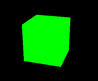
Go into the folder
02-simple-shader, open the DBPro project and compile and run the program. You should get something like the following:
Go ahead and open the file
simple-shader.fx with a text editor. I prefer using
Notepad++, with the
HLSL syntax highlighting plugin.
I
At the very top of your shader are various
shader constants. Some of these are user-defined, and can be set through DBP by using the commands
set effect constant float or
set effect constant vector. This gives you a nice way of controlling parameters from within DBP. Other shader constants gain their values from what's known as
semantics.
In Tutorial 01, we discussed how the vertex shader transformed Bob into world space, then into view space, then into projection space by using matrices. Where do these matrices come from?
Fortunately, they are actually generated automatically by DBP, and there are a bunch of pre-defined semantics for accessing them, one of them being the following:
Make sure to try and implement the stuff below in your
PLAYGROUND folder on your own, so you really understand how it works.
// shader semantics
float4x4 matWorldViewProjection : WORLDVIEWPROJECTION;
As the name implies, the world, view, and projection matrices have all been multiplied together to form a single matrix, unsurprisingly called the
world view projection matrix. If you multiply a vertex by this matrix, you transform it from
object space directly into
projection space, skipping all intermediate projections.
By writing the code above, the variable
matWorldViewProjection will automatically be assigned the world view projection matrix, because
WORLDVIEWPROJECTION is the semantic for said matrix.
For a complete list of semantics, you can look at the official MSDN documentation
here. But don't worry, 95% of the time the world view projection matrix is the only matrix you will ever need.
The next thing we need is to consider the data going in and out of the vertex and pixel shader programs.
We know the vertex shader "does things" with vertices. For instance, it can transform vertex positions into different 3D spaces, like it did with Bob.
In our case, all we really need are the
position attributes of each vertex as input:
struct VS_INPUT
{
	float4 position : POSITION0;
};
As you can see, we're using the pre-defined semantic
POSITION0, which automatically reads the position attribute from the current vertex being processed and assigns it to the variable
position located in our struct
VS_INPUT.
From our vertex shader, we'll want to output the new position of the vertex after transforming it. Again, we'll make a struct for handling that:
struct VS_OUTPUT
{
	float4 position : POSITION0;
};
As you can see, we're using the pre-defined semantic
POSITION0, which automatically assigns the position attribute of the current vertex being processed.
You'll notice the semantics have a leading "0". A vertex has various
stages. The position of the vertex is written to stage 0 of the object. Theoretically it is possible to have a vertex with multiple positions, but frankly, that's retarded, so we only read from stage 0.
Next, the input of the pixel shader program. Since this is the simplest of shaders, there is nothing to input, so we'll just leave it blank:
Last but not least, we need to define the output values of the pixel shader program. In almost all cases, the only thing you'll ever want to output is the final colour.
struct PS_OUTPUT
{
float4 colour : COLOR;
};
Again, note the use of the
COLOR semantic, which assigns the output colour attribute of the render target to the variable
colour.
Now it's time to write the vertex shader program. Here it is.
VS_OUTPUT vs_main( VS_INPUT input )
{
// declare output struct, so we can write output data
VS_OUTPUT output;
// take each position attribute of the incoming vertex and transform it into projection space
output.position = mul( input.position, matWorldViewProjection );
// return output data
return output;
}
This little section of code is where all of our vertex manipulation happens. In our case, we transform all vertices into projection space, as discussed in Tutorial 01, by multiplying each vertex by the world view projection matrix.
Very important to understand: The vertex shader is
executed once for every vertex of the object. This means that if your object has 36 vertices,
vs_main is called 36 times, and every time it's called, the variable
input.position contains the position of the active vertex. You may have guessed it: Yes, all 36 instances of vs_main are executed in parallel, one on each core of the GPU. Since the GPU has thousands of cores, even an object with tens of thousands of vertices will only take a fraction of a microsecond to compute.
Next up, we need a pixel shader. Here it is.
PS_OUTPUT ps_main( PS_INPUT input )
{
// declare output struct, so we can write output data
PS_OUTPUT output;
// this is a very simple shader. colour every pixel green
output.colour = float4( 0.0f, 1.0f, 0.0f, 1.0f );
// return output data
return output;
}
This little section of code is where all of our pixel manipulation happens. In our case, we simply set every pixel to have the colour green.
Very important to understand: The pixel shader is
executed once for every pixel. This means that
ps_main will be called once for every pixel on the screen that is part of that object. If you had a 1920x1080 display, and the object were close enough to the camera to cover it entirely,
ps_main would be called 1920x1080=2073600 times. You may have also guessed this one: Yes, all 2073600 instances of ps_main are executed in parallel, one on each core of the GPU.
Obviously, the GPU may not have 2073600 cores, in which case the programs are simply queued up so there are always a maximum number of them instantiated. The order in which this happens is undefined.
The very last thing to do is to tell DBP how to compile and execute the vertex and pixel shader programs. This is done by defining a
technique and a number of
passes.
technique Default
{
pass p0
{
VertexShader = compile vs_1_1 vs_main();
PixelShader = compile ps_1_1 ps_main();
}
}
Here, you are looking at a technique containing a single pass, which compiles the vertex and pixel shader programs above using shader model 1.1. Basically, the lower the shader model version, the more hardware you'll be able to support, but the less shader features you'll be able to use.
DBP supports up to shader model 3.0.
Summary
* A
vertex shader is used to transform an object from
object space into another space (most commonly
projection space), and can also be used to manipulate vertex attributes.
* A
pixel shader is used to manipulate the colour of an object's surface at a per-pixel basis.
* A
semantic can be used to access important shader constants such as vertex attributes or transformation matrices, and assign them to variables.
* Vertex and pixel shader programs are executed
in parallel: A vertex shader program for every vertex, and a pixel shader program for every pixel on the screen.
Here is the entire shader from above:
// ----------------------------------------------------------------------------
// Projection matrices
// ----------------------------------------------------------------------------
float4x4 matWorldViewProjection : WORLDVIEWPROJECTION;
// ----------------------------------------------------------------------------
// Input and output structs
// ----------------------------------------------------------------------------
struct VS_INPUT
{
float4 position : POSITION0;
};
struct VS_OUTPUT
{
float4 position : POSITION0;
};
struct PS_INPUT
{
};
struct PS_OUTPUT
{
	float4 colour : COLOR;
};
// ----------------------------------------------------------------------------
// Vertex shader
// ----------------------------------------------------------------------------
VS_OUTPUT vs_main( VS_INPUT input )
{
	// declare output struct, so we can write output data
	VS_OUTPUT output;

	// take each position attribute of the incoming vertex and transform it into projection space
	output.position = mul( input.position, matWorldViewProjection );

	// return output data
	return output;
}
// ----------------------------------------------------------------------------
// Pixel shader
// ----------------------------------------------------------------------------
PS_OUTPUT ps_main( PS_INPUT input )
{
	// declare output struct, so we can write output data
	PS_OUTPUT output;

	// this is a very simple shader. colour every pixel green
	output.colour = float4( 0.0f, 1.0f, 0.0f, 1.0f );

	// return output data
	return output;
}
// ----------------------------------------------------------------------------
// Techniques
// ----------------------------------------------------------------------------
technique Default
{
	pass p0
	{
		VertexShader = compile vs_1_1 vs_main();
		PixelShader = compile ps_1_1 ps_main();
	}
}
Proceed to the next tutorial:
03 - Vertex Shader Coordinate System
Proceed to the previous tutorial here:
01 - Understanding The Graphics Pipeline
TheComet
Your mod has been erased by a signature